

TaC Coated Susceptor Manufacturer You Can Rely on for High-Temperature CVD
2026-09-27
High-temperature CVD doesn't forgive shortcuts—especially when it comes to the susceptor. Cracks, delamination, and contamination can derail an entire batch, so finding a TaC coated susceptor manufacturer you can rely on isn't just nice to have; it's essential. Semicorex has built its reputation around this exact challenge, delivering TaC coatings that stay stable under extreme thermal and chemical stress. In this article, you'll see why that matters for your process.
Why Standard Graphite Susceptors Fail Early in High-Temperature CVD
Standard graphite susceptors in high-temperature CVD processes typically operate above 1200°C, with some recipes pushing close to 1600°C. While graphite offers excellent high-temperature stability, commercial grades are inherently porous and have oriented grain structures, which makes local thermal conductivity and thermal expansion highly non-uniform. During rapid heating or cooling, the differential expansion between adjacent regions builds internal stress concentrations, and because graphite is brittle, this stress cannot be relieved through plastic flow. As a result, microcracks appear at susceptor edges and around support holes far earlier than the designed lifetime, and these cracks then provide pathways for reactive gas penetration and further degradation.
Another accelerating factor is the interface between the protective coating and the graphite substrate. Many standard graphite susceptors are coated with SiC or pyrolytic carbon to reduce particle shedding and gas attack, but the thermal expansion coefficients of these coatings never perfectly match the graphite underneath. At high temperature, shear stress at the coating-substrate interface causes small delaminations. Once pinholes or localized spalling occur, corrosive gases such as ammonia, hydrogen, or metal halide precursors come into direct contact with bare graphite. The chemical inertness of graphite toward these gases is in fact limited at elevated temperatures, especially when catalytic metal impurities are present. Carbon can be rapidly oxidized or converted to volatile carbides, leading to local wall thinning and shifts in electrical resistance distribution.
In addition, standard graphite susceptors undergo grain growth and impurity migration during extended high-temperature operation. Metallic impurities like iron, nickel, and calcium tend to segregate toward the surface, where they not only weaken the mechanical strength but also act as unintended nucleation sites during CVD reactions. This causes non-uniform film thickness and localized hot spots. Those hot spots, in turn, intensify thermal stress and create a positive feedback loop. Within only a few dozen process cycles, the susceptor can warp, crack, or even fracture. Thus, standard graphite susceptors rarely fail from a single cause; instead, thermal, chemical, and mechanical effects combine to drive early degradation.
The TaC Coating Difference That Keeps Bond Strength and Purity Intact
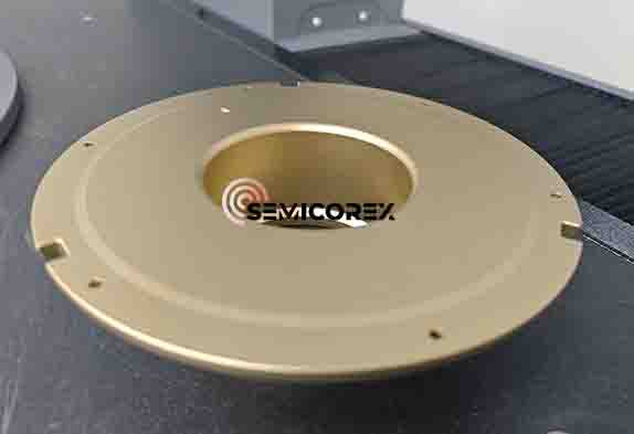
Tantalum carbide coatings stand apart because they don't just sit on the surface—they integrate with the substrate at a level that preserves both mechanical grip and chemical cleanliness. Most barrier layers trade one for the other: a tough bond often introduces impurities, while an ultra-pure film tends to peel under stress. TaC sidesteps this compromise by forming a dense, columnar microstructure that interlocks with the base material, so adhesion stays high even during thermal cycling. At the same time, the coating's stoichiometry resists harmful diffusion, keeping the underlying surface free from contamination without sacrificing the strength of that interfacial hold.
What makes this balance possible is the way TaC handles temperature and aggressive environments. Unlike coatings that oxidize or react at elevated heat, tantalum carbide remains stable and maintains its integrity, preventing the kind of micro-cracking that gradually separates a layer from its foundation. This means components keep their bond strength over thousands of cycles, not just in a single test. Meanwhile, the low vapor pressure and non-reactive nature of the coating mean no unwanted elements bleed into the process, so purity stays intact from the first run to the last.
In practical terms, this difference shows up where it matters most: in crucibles, susceptors, and other high-stakes surfaces, the coating doesn't flake or spall, and it doesn't introduce trace metals or carbon contamination. Engineers see fewer rejects, longer service intervals, and a more predictable process. The TaC layer essentially becomes a quiet, reliable partner—holding tight where bonds must not fail, and staying pure where even a few parts per billion can ruin a batch.
How We Match Coating Thickness to Your Process Gas Chemistry
Coating thickness isn't a one-size-fits-all number. We start by mapping the molecular weight, reactivity, and diffusion behavior of your process gas against the substrate's thermal and mechanical profile. That tells us whether a thin, dense barrier will outperform a thicker, more porous layer—or vice versa. For aggressive halide chemistries, thicker isn't always better; we often tune a graded interface so the outermost few hundred nanometers handle the harshest exposure while the underlying layers stay resilient.
We also look at how gas composition changes across your temperature window. A recipe that runs clean at 600°C may become corrosive at 800°C if trace moisture or oxygen sneaks in. By adjusting coating thickness in response to those equilibrium shifts—sometimes just 10–15% thicker on the hot zone—we extend component life without overbuilding the entire surface. It's a balancing act between chemical resistance, adhesion stress, and thermal expansion mismatch.
Every thickness recommendation we deliver comes from a combination of thermodynamic calculations and real furnace data, not generic lookup tables. If your process gas includes mixed acids, organometallics, or cyclic reduction-oxidation steps, we simulate the layer-by-layer consumption rate before we ever cut metal. That way the coating thickness we quote reflects what actually happens in your chamber, not what happens in someone else's brochure.
Custom Susceptor Geometries That Survive Thermal Cycling Without Cracking
Susceptors often fail because sharp corners and abrupt thickness changes concentrate thermal stress during rapid heating and cooling. By replacing these features with continuously curved fillets, blended radii, and gradually tapered cross-sections, engineers can spread stress over a wider area instead of letting it spike at a single edge. This approach works particularly well for large-diameter susceptors used in epitaxial reactors, where the temperature delta between the center and the rim can exceed several hundred degrees Celsius within seconds.
Another practical strategy involves asymmetric mass distribution and stress-relief cutouts that allow the wafer pocket region to expand and contract independently from the outer ring. A shallow, spiraling groove machined on the backside can act as a controlled flexure, absorbing thermal deformation without compromising flatness. Some custom designs also use variable pocket depth or a dished profile that pre-compensates for thermal bow, so the susceptor stays flat at operating temperature rather than at room temperature.
Validation of these geometries typically combines finite element analysis of thermal gradients with repeated cycling tests in a controlled furnace. A well-tuned custom shape will show a dramatically lower peak tensile stress compared to a standard flat disk, often moving the failure point away from the wafer pocket and into a low-stress support region. This lets the susceptor survive hundreds of cycles while maintaining dimensional stability, making it a reliable choice for high-throughput semiconductor processing.
What Long-Running MOCVD and SiC CVD Tools Reveal About Susceptor Life
What begins as a pristine graphite core with a dense SiC or TaC coating eventually tells a story through its wear patterns. Long-running MOCVD tools show that susceptor degradation rarely follows a linear path. Early cycles produce minor surface oxidation, but after hundreds of thermal cycles, micro-cracks open along coating grain boundaries. These cracks let process gases reach the graphite underneath, causing localized pitting. Once pitting starts, the affected pockets become particle sources that can transfer to wafers, and uniformity drifts even before coating thickness is fully consumed.
In SiC CVD systems, where susceptors are pushed to 1600°C or higher, the failure modes are slightly different. The coating may remain visually intact while the graphite core slowly changes its thermal conductivity due to repeated phase transformations and impurity migration. A susceptor that looks acceptable under bench inspection can produce a hot spot large enough to shift doping or thickness profiles across the wafer. Long tool runs reveal these shifts as gradual, not sudden, which is why monitoring sheet resistance or epi thickness alone can miss early warning signs.
Practical experience from extended campaigns shows that susceptor life is best predicted by combining visual inspection with thermal mapping and particle counts. Facilities that track wafer-to-wafer temperature offsets and backside deposition patterns tend to replace susceptors before yield loss becomes obvious. The real value of long-running tools is not just longer intervals between replacements, but the dataset they generate: it turns susceptor aging from a guessed maintenance item into a predictable consumable with well-defined end-of-life criteria.
Questions to Ask a TaC Coated Susceptor Manufacturer Before You Commit
Start by pinning down the exact coating parameters—ask what deposition temperature they run, which precursor gases they use, and how they control thickness across the entire susceptor surface. A shop that hesitates to share these numbers or defaults to “proprietary blend” without any supporting data is often hiding uneven coverage or poor adhesion. Request a cross-sectional SEM image from a recent batch, not a brochure photo, and check for cracks, voids, or delamination at the TaC-graphite interface.
Next, dig into real-world thermal cycling performance. How many cycles has their coating survived in a production MOCVD reactor under your target temperature? Can they provide a log of thickness loss over time, or at least weight-change data after repeated heating and cooling? If they only quote a theoretical lifespan based on lab coupons, treat that as a starting point, not a guarantee. Ask for contact information of a customer running a similar process, and call them.
Finally, never sign off without clarifying tolerances, lead times, and what happens after delivery. Will they machine the susceptor to your pocket dimensions after coating, or do you need to send a drawing first? What is their re-coating policy if the layer fails prematurely—do they strip and reapply, or demand a new purchase? Get the warranty terms in writing, including exclusions for thermal shock or cleaning damage, and confirm whether they offer failure analysis if the coating spalls within the first month.
FAQ
Tantalum carbide holds up under temperatures that turn most other coatings into a liability. It resists thermal shock, stays chemically stable in aggressive process gases, and doesn't shed particles that could ruin wafer yield. For us, that means we can run longer deposition cycles without constantly swapping parts or fighting drift.
We match the coating's thermal expansion behavior to the substrate from the start, then use a multi-stage densification process to remove porosity. After coating, every susceptor goes through thermal cycling tests that go beyond typical operating limits, so a part doesn't leave our floor until it has proven it can survive the ramp rates your reactor demands.
You'll see it in silicon carbide epitaxy, GaN-on-Si growth, and other wide-bandgap semiconductor processes where the wafer carrier sits above 1,500°C for long runs. Customers in power electronics and LED production come to us because their process window doesn't forgive contamination or dimensional change.
Yes, we start from your drawings or even a worn sample and reverse-engineer the critical dimensions. Pocket depth, edge profile, and coating thickness are all adjustable, so you get a drop-in part that works with existing gas flow patterns instead of forcing you to retune the process.
You want a surface that supports uniform film nucleation without being so smooth it causes the wafer to stick or slide unpredictably. We typically hold Ra below 0.8 µm on the coated face, but we can adjust roughness within a narrow band to match your precursor chemistry and avoid edge buildup.
We combine ultrasonic inspection with a surface resistivity map across the entire coated area. Any region that shows abnormal conductivity or a subsurface void gets rejected or reworked, because a pinhole in TaC can become a carbon contamination source at operating temperature.
We keep a record of each part's coating lot and test results, so if you see a performance shift months later, we can trace it back. We also offer periodic recoating and dimensional checks for customers running multiple reactors, which often extends the total service life by a significant margin.
Conclusion
When standard graphite susceptors are pushed in high-temperature CVD processes, they often fail early because unprotected carbon reacts with aggressive process gases, leading to particle generation, dimensional drift, and premature breakage. A reliable TaC coated susceptor manufacturer addresses this by applying a dense, stoichiometric tantalum carbide layer that maintains bond strength and purity even after repeated thermal cycling. The coating is not a generic overlay; its thickness is carefully matched to the specific gas chemistry—whether hydrogen-rich MOCVD or chlorine-based SiC epitaxy—so that diffusion barriers remain intact and no underlying graphite is exposed. This tailored approach prevents the coating from spalling or cracking when the susceptor is rapidly heated and cooled, which is a common failure mode in poorly engineered parts.
Beyond material science, a dependable supplier offers custom susceptor geometries that are machined and coated to survive the stresses of high-frequency thermal cycling without cracking. Long-running tools in MOCVD and SiC CVD reveal that susceptor life is not just about the coating thickness but also about edge coverage, pocket design, and pre-coating surface preparation. Before committing to a manufacturer, serious buyers ask pointed questions: How do you verify coating adhesion after thermal shock? What is the maximum allowable defect density in the TaC layer? Can you provide reference data from production reactors with similar gas flows? A manufacturer that can answer these with transparent process documentation and field-proven results is the one you can rely on for high-temperature CVD, because their susceptors consistently deliver longer campaigns, lower particle counts, and more stable wafer temperature uniformity.
Contact Us
Contact Person: Svenja Wei
Email: [email protected]
Tel/WhatsApp: +8613567891907
Website: https://www.semicorex.com